


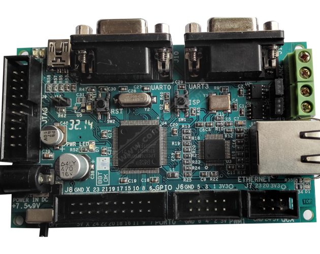
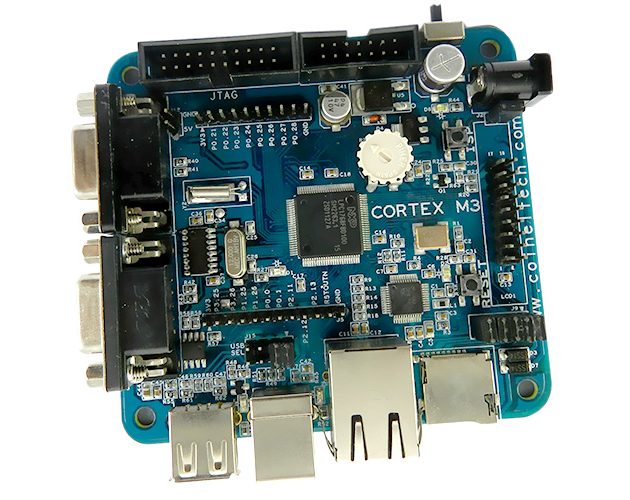
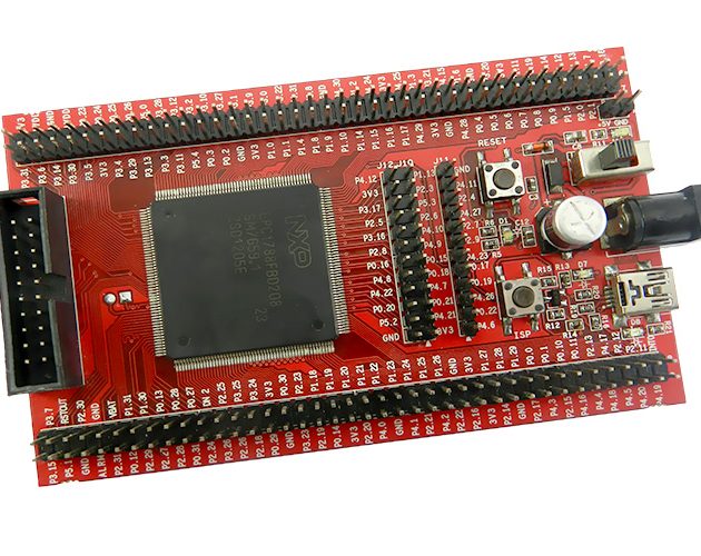
LPC1788/LPC4088 MiO Board
₹11,000.00
- Description
- Additional information
- Downloads
- Media/Videos
- Additional Information
- Reviews (0)
- Download
Description
The LPC1788/4088 MiO is based on Cortex M3/M4 Core, running at up to 120MHz.The MiO lets you quickly start with your development on these microcontrollers
| Microcontroller | Core Details |
| LPC1788 | ARM Cortex M3 |
| LPC4088 | ARM Cortex M4 |
The sample code is provided for every peripheral that’s on board. Along with it, the schematic, required software and tools are provided using which you can start with your application development from day one.
The MIO board is suitable for various advanced applications that require high end display connectivity options.
The MiO has a 20 pin Wiggler-compatible JTAG interface and a SWD interface which can be used for debugging/programming.
The board can be debugged/programmed using parallel JTAG, CoiNel USB JTAG and other compatible debuggers like ULink2, ULink Me, ULink Pro, JLink ARM, Red Probe etc.
Note: Display Options for MiO are sold separately and are not the part of MiO Package.
Features of MiO
- MCU:
- LPC1788. Package: BGA-208.
- LPC4088. Package: BGA-208.
NOTE: Choose the MCU based on your requirement
- External SDRAM – MT48LC64M4A2 (256 MBits X 2)
- FLASH – AT25DF641, Interface – SPI (optional)
- 20 PIN 2.54 mm JTAG Header, 10 pin 1.27mm SWD/JTAG Connectivity options.
- On Board Reset and ISP
- On Board 12 Mhz Clock
- On Board 32.768 Khz Clock for RTC
- MicroSD Card Interface via MCI
- Option to connect Graphical LCD (TM12864H6CCOWA).
- On Board Test LED and Buzzer
- USB Device (USB1)
- USB Host (USB1 and USB2)
- On Board POT connected via ADC 0.0
- On Board CAN Transceiver (MCP2551) – CAN1
- 2 x UART (RS232) – UART0 and UART2 + TTL Outputs for UART0 and UART2
- On Board PS2 Keyboard Connectivity Option
- Two switches via GPIO
- Ethernet Connectivity via DP83848 PHY
- 40 PIN TFT (24 Bit datalines) Header including SPI and I2C on same header
- Audio Amplifier. Connected via DAC Out with 3.5mm audio jack.
- Pin Outs for GPIO including I2c, SPI, ADC etc
- Internal RTC with CMOS Battery (2032) Connectivity Options.
- On Board Power Supply for 5V and 3.3V
TFT Display Options for MiO Board.
3.2 inch TFT
3.5 inch TFT
4.3 inch TFT
5.7 inch TFT
7 inch TFT
Graphical Display Options for MiO Board.
TM12864H6CCOWA
KEY DELIVARABLES
- LPC1788 or LPC4088 MiO Board
- USB A to B Cable
- 7.5 V/1Amp Adapter
Parallel Port JTAG (tested on Keil uvision4.53 IDE, Rowley Crossworks)
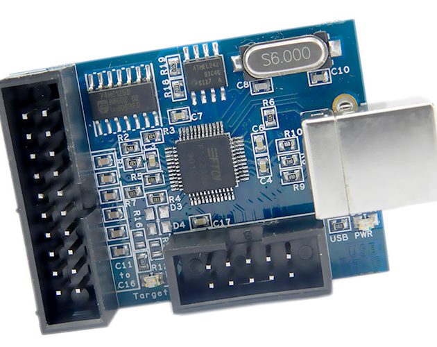
CoiNel ARM USB JTAG (tested on Rowley CrossWorks)
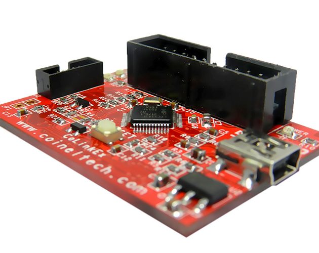
CoiNel CoLinkEx (tested on Keil)
The Board can also be used with other compatible JTAG Debuggers.
The details on how to use the JTAG and its associated plugins are provided with the documents and also can be downloaded from Download section.
ISP Programming:
Programming can be done through the on chip boot loader using UART interface (UART0). You will have to use a TTL to RS232 Converter to do so since the pinout are TTL logic and PC uses RS232 logic. The tool used for programming is Flash Magic.
Programming Using CoFlash
The controller can be Programmed using CoFlash from CooCox. The binary file needs to loaded using this tool. You can download the tool in the download section.
To use CoFlash, you would need CoiNel ARM USB JTAG or CoiNel CoLinkEx.
USB Boot Loader
The Board can also be programmed via USB Secondary Bootloader. Check LPC1788 USB Boot Loader document for more details.
We currently have bootloader support for LPC1788 Only
TOOLS:
Our products can be used with majority of IDE that support Cortex M3 Family. A few IDE and plugin details are given below.
- Keil uvision4.53 IDE (32K code limited version can be used. Use 4.53 and above)
- Rowley Crossworks (30 day evaluation version can be used.)
- IAR workbench (32K code limited version could be used.)
- CooCox CoIDE (Unlimited, Open Source)
Plugins/Programmers:
H-JTAG, CooCox Colink, Flash Magic have been tested.
Compatible debuggers like U-Link, J-Link etc can also be used.
- ARM Cortex M3 Core
- Upto 120 MHz Operation
- Nested Vector Interrupt Controller (NVIC) for fast deterministic interrupts.
- Wakeup Interrupt Controller allows automatic wakeup from any priority interrupts.
- Memory Protection Unit.
- Four reduced power modes – sleep, deep sleep, power down, deep power down.
- Memories
- 512 KB Flash.
- 96 KB SRAM
- 4 KB EEPROM
- Serial Peripherals
- 10/100 Ethernet MAC
- Two Full Speed USB
- Four UART and one USART
- Two CAN 2.0B controllers.
- Three SSP/SPI controllers.
- Three I2C Interface.
- I2S Interface for digital Audio.
- ANALOG Peripherals
- ADC – 12 Bit with eight Channels
- DAC – 10 Bit, One channel
- Other Peripherals
- LCD controller, supporting both STN and TFT displays
- RTC with event recorder for tamper detection.
- Eight channel DMA Controller
- Upto 165 GPIO
- Motor Control PWM with quadrature encoder interface.
- Four 32 Bit General purpose Timer/Counter with eight capture and 10 compare outputs.
Difference between LPC1788 and LPC4088 is
- LPC4088 has Digital Signal Processing Capabilities (Check Datasheet for details)
- LPC4088 has SPIFI peripheral. If you have lots of graphics images you can store them inside serial flash, which is mapped in microcontroller’s memory map.
Additional information
| Weight | 0.250 kg |
|---|
Downloads
DOCUMENTATION
MCU Related
| Datasheet for LPC1768(pdf, 823 KB) |
| User Manual of LPC1768(pdf, 5059 KB) |
| Errata Sheet for LPC1768(pdf, 142 KB) |
| Cortex M3 Technical Reference Document(pdf, 2.14 MB) |
| Application Notes on LPC1700 MCU (WinZip, 2.90 MB) |
Product Related
| Overview on LPC1768 Header Board(pdf, 492 KB) |
| Schematic for LPC1768 Header Board(pdf, 43 KB) |
| User Manual on How to use USB Bootloader for LPC1768(pdf, 417 KB) |
Programming Related
| HJTAG Installation and Configuration Guide(pdf, 804 KB) |
| Creating Project on Keil uVision(pdf, 3896 KB) |
| Installation Guide for Rowley Crossworks(pdf, 395 KB) |
| Creating project in Rowley Crossworks(pdf, 765 KB) |
| Configuration and Usage of Parallel Port JTAG with HJTAG plugin on Keil(pdf, 870 KB) |
| Using CoiNel CoLinkEx Debugger with CooCox CoLinkEx plugin on Keil MDK(pdf, 2053 KB) |
| Using CoiNel ARM USB JTAG with CooCox CoLink on Keil MDK(pdf, 667 KB) |
SAMPLE SOURCE CODE
| USB Bootloader Hex File for LPC1768 (WinZip, 9 KB) |
| Sample Source Code Bundle for LPC1768 Header Board (WinZip, 1352 KB) |
DRIVERS
| Driver needed for USB Device (Virtual COM Configuration) (WinZip, 2291 KB) |
SOFTWARE TOOLS
| Keil uVision IDE download link for 32 BIT ARM (32K limited version) (Weblink) |
| Rowley Crossworks download link (1 month evaluation version) (Weblink) |
| IAR Workbench download link (32K limited Version) (Weblink) |
| Flash Magic-Standalone Programmer (Weblink) |
| HJTAG Plugin download link (Weblink) |
| CooCox Plugin (Ver 1.4.2.1) tool for CoLinkEx with Keil MDK (Exe File, 676 KB) |
| CoLinkEx USB Driver (Ver 1.2.1) for CoLink Ex. Note: Connect Hardware while Installing (Exe File, 15.4 MB) |
| CooCox IDE Setup File (Exe File, 131 MB) |
| CoFlash (Ver 1.4.2.1) Standalone Programmer (Exe File, 1.8 MB) |
Media/Videos
Additional Information
Precautions on use
- Be sure to read the catalogue and instruction manual before using this product. Incorrect usage could lead to an electric shock, damage to the product or a fire hazard.
- Use this product within the specified input voltage, output power, output voltage, output current, and range of ambient temperature/ambient humidity. Using this product in conditions beyond the specification limits can shorten the lifetime of the product, or can cause, damage to the product.
- intrusion of foreign matter (On print head) can cause abnormal wear and reduce service life.
- Clean the print head regularly with a clean cloth. Use IP if necessary. Put some IP on the cloth and gently clean the print head.
- Use Good Quality Thermal Paper. While cutting the paper, the small particles tend to gather on the print head and can reduce print head life.
- Do not use the product at temperature of 50℃ or higher. Exposure to higher temperatures may cause malfunction, parts to deform/be damaged.
- Donot use the product if it is used in an environment where cutting chips, corrosive solvents, water, etc., may enter the product.
- Do not use undue force when removing cover for paper insertion. This can damage the plastic part.
- Malfunction and failure may be caused if this product is used in environments with conductive substances or dust.
- Be sure to take protective measures against the surge voltage caused by lightning, etc. Damage to the unit may be caused due to irregular voltage.
- Please contact CoiNel or its authorized service centers if any malfunction occurs; do not open the product yourself.
Precautions on Handling
- Donot modify, disassemble, or open this product. This will result in loss of functionality.
- Take care not to drop or strike the product. Doing so may cause injury or damage. Giving an impact to it could also cause damage to its function even if the product looks intact.
The manufacturer’s warranty will not cover any required characteristics of this product if it is used under conditions that are beyond specifications or donot meet the precautions or handling criteria for the product.
The information in the catalogue is subject to change without prior notice.
You may also like…
Related products
Reviews
There are no reviews yet.